


Comprehensive Automotive Electrical System
Comprehensive Automotive Electrical System Manufacturer
High Quality Comprehensive Automotive Electrical System
Affordable Comprehensive Automotive Electrical System

Comprehensive Automotive Electrical System Supplier

Comprehensive Automotive Electrical System OEM
Comprehensive Automotive Electrical System
components, showcasing the structure and working processes of various automotive electrical systems, including
the engine anti-theft system, instrument system, lighting system, wiper system, horn system,
ignition system, electric window system, electric door locks, audio system, starting system, and charging
system. It is suitable for schools to teach the theory and maintenance training of the Comprehensive
Automotive Electrical System.
Guangdong Zhongcai Education Equipment Co.,Ltd. is one of the most reliable manufacturers and suppliers of comprehensive automotive electrical system in China. Welcome to buy high quality engineering education equipment from our factory. Also, OEM&ODM service is available.

I. Product Overview
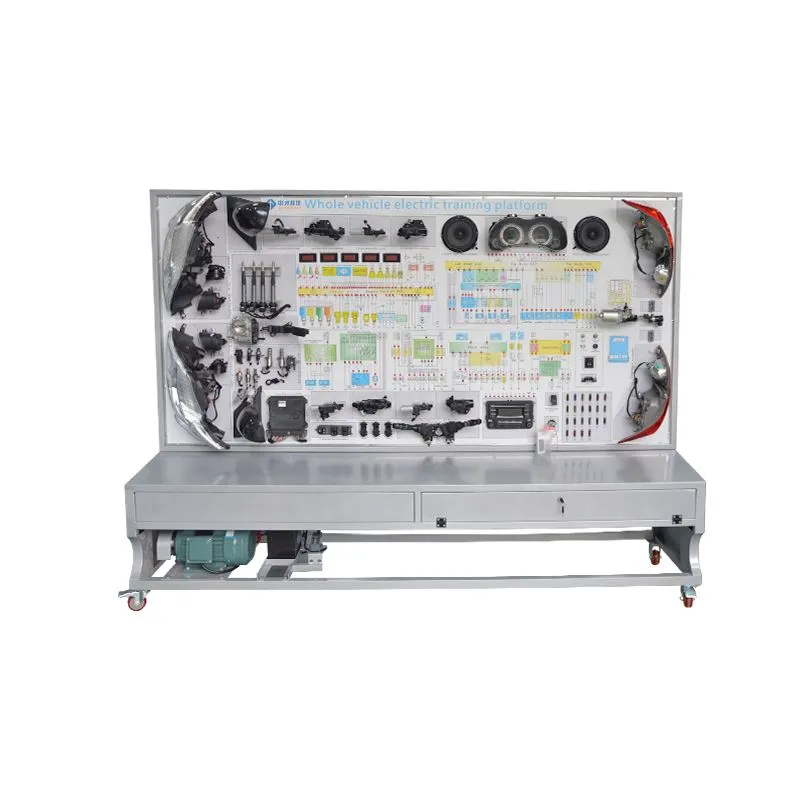
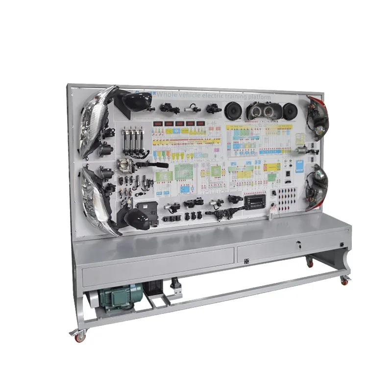
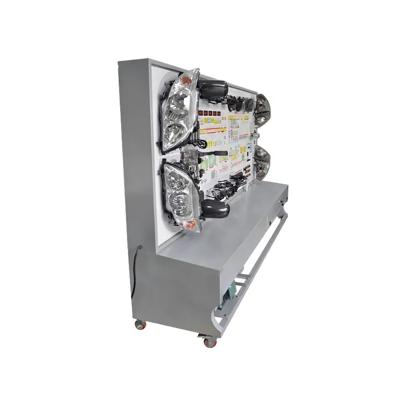
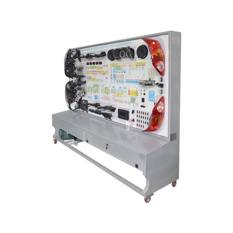
The Comprehensive Automotive Electrical System training platform is based on actual automotive electrical components, showcasing the structure and working processes of various automotive electrical systems, including the engine anti-theft system, instrument system, lighting system, wiper system, horn system, ignition system, electric window system, electric door locks, audio system, starting system, and charging system. It is suitable for schools to teach the theory and maintenance training of the Comprehensive Automotive Electrical System.
II. Product Features
Real and operational automotive electrical systems that fully demonstrate the composition and structure of the Comprehensive Automotive Electrical System.
Connect the power supply and operate various electrical switches and buttons on the teaching panel to demonstrate the working processes of the automotive engine electronic control system, instrument system, lighting system, wiper system, horn system, ignition system, electric window system, electric door locks, audio system, starting system, and charging system.
The equipment panel is made of high-grade aluminum composite material that is impact-resistant, pollution-resistant, fire-resistant, and moisture-resistant. The surface undergoes a special spray coating treatment; the panel is printed with a color circuit diagram that does not fade. Students can intuitively compare the circuit diagram with the actual components to understand and analyze the working principles of each automotive electrical system.
The teaching panel is equipped with detection terminals that allow direct measurement of electrical signals from the circuit components of automotive electrical systems, such as resistance, voltage, current, and frequency signals.
The panel includes a diagnostic socket that can connect to dedicated or universal automotive decoders for ECU coding queries, reading and clearing fault codes, reading data streams, component testing, parameter setting, waveform analysis, and key matching.
The panel features a 1.5mm cold-rolled steel structure for aesthetic appeal; the base is made from welded steel, with a spray coating process and self-locking casters for mobility.
III. Technical Specifications
Dimensions (approx.): 2400×700×1900mm (L×W×H);
Power Supply: Three-phase four-wire (or three-phase five-wire) 380V ±10%, 50Hz;
Operating Voltage: DC 12V;
Operating Temperature: -40℃ to +50℃;
Three-phase asynchronous motor;
Voltage: AC 220V/380V;
Power: 2.2KW;
Speed: 1420 r/min;
Steel Pipe: 40×40×3mm;
Cabinet: 1.5mm cold-rolled steel stamped structure, with a maintenance door at the back;
Mobile Casters: 100×60mm.
IV. Basic Configuration (per unit)
| No. | Name | Specifications | Unit | Quantity |
| 1 | Teaching Panel | Equipped with various detection terminals and color circuit diagram | Set | 1 |
| 2 | Engine Control Unit (ECU) | Original Vehicle | Set | 1 |
| 3 | Diagnostic Socket | Original Vehicle | Piece | 1 |
| 4 | Ignition Switch | Original Vehicle | Piece | 1 |
| 5 | Combination Instrument | Original Vehicle | Set | 1 |
| 6 | Combination Switch | Original Vehicle | Set | 1 |
| 7 | Left and Right Front Headlight Assembly | Original Vehicle | Set | 1 |
| 8 | Left and Right Fog Lights | Original Vehicle | Set | 1 |
| 9 | Left and Right Turn Signal Lights | Original Vehicle | Set | 1 |
| 10 | Left and Right Side Marker Lights | Original Vehicle | Set | 1 |
| 11 | Left and Right Combination Tail Lights | Original Vehicle | Set | 1 |
| 12 | License Plate Light | Original Vehicle | Set | 1 |
| 13 | High-Level Brake Light | Original Vehicle | Piece | 1 |
| 14 | Light Switch | Original Vehicle | Set | 1 |
| 15 | Brake Light Switch | Original Vehicle | Set | 1 |
| 16 | Reversing Light Switch | Original Vehicle | Set | 1 |
| 17 | Hazard Light Switch | Original Vehicle | Set | 1 |
| 18 | Wiring Harness | Original Vehicle | Set | 1 |
| 19 | Wiper Assembly | Original Vehicle | Set | 1 |
| 20 | Wiper Controller | Original Vehicle | Set | 1 |
| 21 | Spraying Motor | Original Vehicle | Set | 1 |
| 22 | Spraying Tank | Original Vehicle | Set | 1 |
| 23 | Horn | Original Vehicle | Piece | 2 |
| 24 | Horn Relay | Original Vehicle | Piece | 1 |
| 25 | X-Contact Relay | Original Vehicle | Piece | 1 |
| 26 | Fog Light Relay | Original Vehicle | Piece | 1 |
| 27 | Ignition System without Distributor |
Including Ignition Assembly, Spark Plugs, Crankshaft Position Sensor |
Set | 1 |
| 28 | Simulated Fuel Injector Indicator | Set | 1 | |
| 29 | Fuel Pump Relay | Original Vehicle | Piece | 1 |
| 30 | Fuel Pump Indicator | Original Vehicle | Piece | 1 |
| 31 | Crankshaft Position Sensor and Signal Wheel | Original Vehicle | Set | 1 |
| 32 | Electric Window Main Switch | Original Vehicle | Set | 1 |
| 33 | Left and Right Front Door Computers | Original Vehicle | Piece | 1 |
| 34 | Comfort Computer | Original Vehicle | Piece | 1 |
| 35 | Right Front Door Lock Motor | Original Vehicle | Set | 1 |
| 36 | Left and Right Rear Electric Window Motors | Original Vehicle | Set | 1 |
| 37 | Left and Right Rear Electric Window Switches | Original Vehicle | Set | 1 |
| 38 | Left and Right Rear Door Lock Motors | Original Vehicle | Set | 1 |
| 39 | Automotive Audio Assembly | Original Vehicle | Set | 1 |
| 40 | Speaker | 6", 200W | Set | 1 |
| 41 | Starter Assembly | Original Vehicle | Piece | 1 |
| 42 | Generator Assembly | Original Vehicle | Piece | 1 |
| 43 | Three-Phase Asynchronous Motor | YT 100L1-4 | Piece | 1 |
| 44 | Battery | 12V 45Ah | Piece | 1 |
| 45 | Fuse Box | Piece | 1 | |
| 46 | Main Power Switch | 50A | Piece | 1 |
| 47 | Mobile Platform (with self-locking caster) | 2080×700×1800mm (L×W×H) | Piece | 1 |
| 48 | Fault Simulation and Diagnosis Device | Set | 1 | |
| 49 | Teacher's Manual | Set | 1 | |
| 50 | Certificate and Warranty Card | Set | 1 |
iV.Equipment Handling Precautions
Avoid moving equipment alone during transport. Most of our products are equipped with mobile casters, and the equipment is generally large and heavy.
Automotive training aids often have irregular shapes. Before moving a product, check for protruding objects like nails or sharp edges to prevent injury. If conditions allow, consider wearing protective gloves and shoes.
Do not move equipment quickly over any terrain, as this can lead to loss of control and serious safety accidents, as well as significant damage to the equipment.
Be particularly careful when moving equipment over workbenches, ramps, stairs, and other slippery areas. When transporting equipment through doorways, ensure the door width is sufficient to prevent injury to fingers.
When choosing a placement area, select a flat, ventilated space with shelter and fire safety access. Once a stopping position is confirmed, engage the brakes on the mobile casters or block them with a solid object to prevent rolling. Most of our products must be placed horizontally to operate safely and correctly.
Tip: Use mechanical handling whenever possible.
V. Installation and Debugging Precautions
Non-professionals are prohibited from installing or debugging the equipment. Professionals must thoroughly understand the device's functions and prohibitions before installation and may contact the manufacturer for technical assistance if necessary.
Ensure the equipment is firmly installed to prevent components from falling and causing injury.
If the product uses a 220V/380V power supply, the power cable must be installed by a qualified electrician. Keep a safe distance from this power source during operation to avoid electric shock.
Unauthorized modifications to this equipment are prohibited.
VI.Usage Precautions
The equipment should be used in a well-ventilated, dry environment. Familiarize yourself with the location and usage of fire extinguishers in the practical training room.
Instructors must participate in our after-sales service training before using the equipment to master the basic operation methods and principles, and they must lead students in educational activities. Students are not allowed to operate the equipment alone.
Before using the equipment, check the power connections and clear any debris from the teaching modules, such as disassembly tools and measuring devices.
Inspect the wear on each module. If any components are damaged, perform maintenance or replace them. Maintenance must not be conducted while the equipment is powered on.
Follow the training area regulations and listen to the instructor's arrangements. In case of an accident, remain calm, disconnect the power if possible, and promptly inform the instructor to evacuate the area.
During normal operation, always be aware of high temperatures, pressures, and speeds to prevent injury and equipment damage. The equipment has heating elements, and touching them during operation is prohibited.
The detection terminals or parallel connectors on the teaching panel are directly connected to control systems, sensors, and actuators for testing only. Please conduct tests in accordance with the instructor's guidance. The use of simple test lamps (only regular bulbs), wires, or conductive metals to connect terminals is strictly prohibited, as this may cause short circuits, erroneous signals, and potentially lead to equipment damage and safety accidents.
After training, turn off the main power supply and ensure the equipment is protected from water and dust.
Regularly maintain the equipment, including replacing antifreeze, gear oil, brake fluid, etc.
Smoking and other dangerous operations, such as open flames, are prohibited near the equipment.
VI.After-Sales Service Philosophy:
The day the product is put into use is our true test. We can never excuse our shortcomings; solving problems is our only option. Providing you with sincere service is our everlasting commitment.
VII.After-Sales Service Process:
You, the customer, will send us an email outlining your after-sales needs.
Upon receiving your email, we will respond promptly and work to resolve the issue as quickly as possible.
We conduct regular follow-ups and track service, always monitoring your usage and providing timely assistance.
Note: We welcome your calls at any time!
Hot Tags: comprehensive automotive electrical system, China, manufacturers, suppliers, engineering, OEM, ODM, four cylinder diesel engine, byd e5 body electrical system training bench, circuit training equipment, CRDI Common Rail Direct Injector System, auto chassis parts, auto steering model
You Might Also Like


Send Inquiry