


Car Training Equipment
New Energy Step-up and Step-down Circuit Connection Training Box
ZC-QCW01A

Product Features
The experimental components and modules are mounted on a plug-in socket system. The reference circuits can be directly connected to the physical layout using the provided instruction manual, enabling one-to-one correspondence between schematic and actual connections. This design enhances understanding, engagement, and hands-on participation.
All components are housed within a sturdy aluminum case featuring a plug-in wiring socket, which allows for convenient future upgrades or the addition of more complex circuit components.
The product utilizes mainstream market components that are compatible with a wide range of standard electrical instruments, allowing formation of various basic circuits used in technician-level
electrical training and teaching demonstrations.
A unified specification plug-in connector system is used, with color differentiation for easy identification. The sockets are equipped with hollow-rivet jacks for smooth plug-in operation. Direct plug-in connections ensure circuit nodes maintain equal potential, simplifying troubleshooting and providing a clear visual understanding of circuit operation.
If components are damaged due to operational errors, they can be easily replaced, significantly improving reusability and long-term value.
Equipment Requirements
The equipment supports the construction of multiple functional circuits in accordance with training requirements, each capable of normal operation and demonstration during instruction.
The supporting plate is made of a specialized PCB board arranged in a rectangular format, with dimensions not less than 30 cm × 30 cm and a thickness of at least 1.6 mm, ensuring durability during repeated use and multiple plug insertions.
The overall design adopts a high-strength aluminum box structure, approximately 35 cm × 35 cm in size, with a reinforced perimeter frame. It features a flat hinge design that allows both sides to open. The interior is lined with black velvet fabric and includes a sewn pocket for organized component storage.
The connecting wires are made from environmentally friendly materials and equipped with plug-in terminals for convenient and reliable connections on the universal board.
A comprehensive training manual is provided in both printed and digital high-definition versions. It guides students step by step through circuit assembly and experimentation. The manual
includes product descriptions, physical structure diagrams, operational guidance, connection exercises, and detailed explanations of working principles.
The connection exercises and working principle demonstrations include six training tasks:
Transformer-diode boost circuit connection
Capacitor-inductor field-effect transistor (FET) boost circuit connection
Mainstream integrated circuit (IC) boost circuit connection
Triode and voltage regulator step-down circuit connection
7800 series integrated chip step-down circuit connection
Resistor voltage divider step-down circuit connection
Basic Experimental Circuits
The platform supports the construction and operation of the following experimental circuits:
Transformer and diode step-up circuit experiment
Capacitor, inductor, and FET step-up circuit experiment
Integrated circuit-based boost circuit experiment
Triode and voltage regulator-based step-down circuit experiment
7800 series integrated chip step-down circuit experiment
Resistor voltage division step-down circuit experiment
Custom circuit design and integration with other circuit systems
Basic Configuration
Each training kit includes:
One aluminum case
One universal baseboard set
One set of electronic components
One set of standard component cards
One set of breadboard wires
One set of plug-in connection wires
One protective circuit set
Note: An operation and service manual must be included with the equipment.
New Energy Rectification and Inversion Circuit Connection Training Box
ZC-QCW02A

Product Features
The experimental components and modules are mounted on plug-in sockets. The reference circuit can be directly connected to the physical layout using the instruction manual. Each component corresponds one-to-one with the diagram, making the learning process intuitive, engaging, and highly participatory.
All components are housed in a durable aluminum box structure equipped with plug-in wiring sockets, allowing easy expansion or addition of more complex circuit components in the future.
The components used in this product are mainstream in the market and compatible with a variety of electrical instruments. They can form the fundamental circuits used in technician-level electrical experiment teaching and demonstration.
A standardized plug-in connector design is adopted, with different colors for easy distinction. Each component socket features a hollow rivet jack for convenient plug-in operation. Direct plug-in connectivity ensures circuit nodes maintain equal potential, simplifying troubleshooting and making circuit observation clear and
straightforward.
If components are damaged due to operational error, they can be easily replaced, significantly improving the reusability and longevity of the equipment.
Equipment Requirements
The system can be used to build circuits with various functions according to instructional needs, ensuring reliable performance during teaching demonstrations.
The supporting plate is made of a high-quality PCB board with a rectangular layout, measuring not less than 30 cm × 30 cm and a thickness of at least 1.6 mm, ensuring durability during repeated plugging and unplugging operations.
The overall structure adopts a high-strength aluminum box design, approximately 35 cm × 35 cm in size, with reinforced framing around the edges. The hinge features a flat opening design that allows both sides to open fully. The interior is lined with black velvet fabric and includes sewn pockets for convenient component storage and organization.
The connecting wires are insulated with environmentally friendly materials and equipped with plug-in terminals, enabling quick and reliable connections on the universal board.
A detailed training guide (provided in both paper and high-definition electronic formats) offers complete instruction for conducting connection experiments. The guide includes product descriptions, physical structure diagrams, usage methods, connection exercises, and
explanations of working principles.
The training guide covers six key tasks:
Half-wave rectifier circuit connection
Full-wave rectifier circuit connection
Chip-based full-wave rectifier circuit connection
Transformer and transistor inverter circuit connection
Chip-controlled inverter circuit connection
Field-effect transistor (FET) inverter circuit connection
Basic Experimental Circuits
The platform supports the construction and testing of the following circuits:
Half-wave rectifier circuit using capacitors and diodes
Full-wave rectifier circuit using capacitors and diodes
PWM-controlled full-wave rectifier circuit using mainstream rectifier chips
Transformer and transistor inverter circuit
Chip-controlled inverter circuit
Inverter circuit using diodes, capacitors, and field-effect transistors
Integration with other circuit systems or user-designed circuits
Basic Configuration
Each training kit includes:
One aluminum box
One universal base plate
One set of electronic components
One set of standard component cards
One set of breadboard wires
One set of plug-in connection wires
One protective circuit set
Note: An Operation and Service Manual must be attached.
New Energy Drive Motor Speed Regulation Circuit Connection Training Box
ZC-QCW03A

Product Features
The experimental components and modules are mounted on plug-in sockets. The reference circuits can be connected to the physical layout using the instruction manual. Each component corresponds directly with the diagram, making the learning process intuitive, engaging, and highly participatory.
All components are installed in a durable aluminum box, equipped with plug-in wiring sockets to allow easy addition of more complex circuit components.
The components are mainstream in the market and compatible with a variety of electrical instruments. They can be used to form basic circuits for technician-level electrical experiment teaching and demonstration.
A standardized plug-in connector system with different colors is adopted. All component sockets use hollow rivet jacks for easy plug-in operation. Direct connections maintain circuit node potentials, simplifying troubleshooting and making the system visually clear.
Damaged components caused by mis operation can be replaced, greatly
enhancing reusability.
The system supports the New Energy Rectifier and Inverter Teaching Resource Package Software V1.0, which uses 3D animation to demonstrate the working principles of DC motor speed regulation circuits.(Not included)
Equipment Requirements
The system allows students to construct circuits with different functions according to teaching requirements, with circuits fully functional for practical learning.
The supporting plate is a specialized PCB board in a rectangular layout, measuring not less than 30 cm × 30 cm with a thickness of at least 1.6 mm, ensuring durability for repeated plug insertions.
The overall structure is a high-strength aluminum box, approximately 35 cm × 35 cm, with reinforced framing. The flat-hinged design allows both sides to open fully. The interior is lined with black velvet fabric and includes sewn pockets for organized component storage.
Connecting wires are environmentally friendly, with plug-in terminals for quick and reliable connections on the universal board.
A detailed practical training guide (provided in both paper and high-definition electronic formats) guides students step by step through circuit connection experiments. The guide includes product introduction, physical structure diagrams, usage instructions, connection e The connection exercises cover five key tasks:
DC drive motor regulation circuit connection
Drive motor forward and reverse regulation circuit connection
Electrolytic capacitor charge and discharge drive circuit connection
DC motor H-bridge drive circuit connection
PWM speed control motor drive circuit connection
Basic Experimental Circuits
The platform supports the construction and testing of the following circuits:
DC drive motor regulation circuit
Drive motor forward and reverse regulation circuit
Electrolytic capacitor charge and discharge drive circuit
DC motor H-bridge drive circuit
PWM speed control motor drive circuit
Integration with other circuits or self-designed circuits
Basic Configuration
The training kit includes:
One aluminum box
One universal base plate
One set of electronic components
One set of standard component cards
One set of breadboard wires
One set of plug-in wires
One set of protection circuits
Note: An Operation and Service Manual must be attached. xercises, and explanations of working principles.
BYD E5 Controller Testing and Disassembly/Assembly Station
ZC-QCG53B

Function Introduction
1. It adopts a new energy vehicle four-in-one controller assembly (with complete accessories, easy to disassemble and assemble) and is mounted on a special flipping frame.
The gearbox is equipped with a speed reduction and tilting mechanism, which allows it to rotate at any angle and lock at any position, making it easy for students to disassemble and assemble from different angles.
2. Place an oil drip tray at the bottom for easy storage of small parts or screws.
3. The tilting frame is constructed with high-strength welded steel and its surface is treated with a spray coating process. The bottom of the tilting frame is equipped with self-locking casters, making it movable and convenient for teaching.
Technical Specifications
Equipment dimensions: 1000×600×1100mm (Length×Width×Height)
Steel pipe: 60*40*3mm
swivel casters
The first two swivel casters have locking function
The two rear swivel casters
The casters are fixed to the frame with M6*4 screws for easy equipment repair and maintenance.
Casters: 60mm × 50mm (diameter × width)
Gearbox: MOPA70; 1:70
Basic Configuration (per unit)
|
Serial Number |
name |
Specifications and Models |
unit |
quantity |
|
1 |
Four-in-one controller assembly |
Complete with accessories, easy to disassemble and test. |
set |
1 |
|
2 |
Disassembly and tilting frame (with self-locking casters), with upright steel pipe 200*200*5mm; |
950×680×850mm (length×width×height), with a speed reducer, capable of rotating and stationary at any axial angle. |
tower |
1 |
|
3 |
Large oil collection basin |
660×590×35mm (Length×Width×Depth) |
indivual |
1 |
|
4 |
Speed reduction mechanism (with hand crank and other accessories) |
|
set |
1 |
BYD E5 Drive Motor Disassembly/Assembly Station
ZC-QCG52B

Function Introduction
1. Adopt the new energy vehicle drive motor assembly (complete with accessories, easy to disassemble and assemble), and mounted on a special flip frame.
The use of reducer flip mechanism, can make the transmission rotate any angle, and can be locked at any position, easy for students to disassemble and assemble from different angles.
2. The bottom is placed in the oil receiving tray, which is convenient for the centralized storage of small parts or screws.
3. The tilting frame is made of high-strength steel structure welded, and the surface is treated by spraying process. The bottom of the flip frame has self-locking casters, which is movable and convenient for teaching.
Technical specifications
Equipment shape: 1000×600×1100mm (L×W×H)
Steel pipe: 60*40*3mm
Universal casters
The first two universal casters with locking function
Two universal casters at the back
The casters are fixed with the table frame by M6*4 screws, which is convenient for equipment repair and maintenance.
Casters: 60mm×50mm(diameter×width)
Speed reducer: MOPA70; 1:70
Basic configuration
|
No. |
Name |
Specification |
Unit |
Quantity |
|
1 |
Drive motor assembly |
set |
1 |
|
|
2 |
Disassembling and turning frame (with self-locking caster device) with column steel pipe 200*200*5mm |
950×680×850mm(L×W×H) with reducer, can do axially any angle of turning and stationary |
set |
1 |
|
3 |
Large catch basin |
660×590×35mm(L×W×D) |
pcs |
1 |
|
4 |
Reduction mechanism (with accessories such as rocker disc) |
set |
1 |
BYD Qin EV Body Electrical System Training Station
ZC-QCD16C

I. Product Requirements
The lighting system training platform is designed based on the interior and exterior lighting and comfort systems of the BYD Qin EV new energy vehicle. It can provide teaching and training in the structural understanding, testing, diagnosis, and repair of the new energy vehicle lighting and comfort systems. The training platform can simulate relevant circuit faults through a fault setter, and after the fault simulation, signals can be measured at the corresponding test terminals on the test panel.
II. Product Functional Requirements
1. It includes a matching headlight assembly. The left and right headlights have independent control units, which can be used for fault diagnosis, fault code data stream reading, and actuator testing via a diagnostic tool. The headlights integrate functions such as parking lights, low beams, high beams, turn signals, and fog lights. The lighting control adopts CAN bus control, which is technologically advanced and functionally stable.
2. The fog light switch can be used to control the headlights, fog lights, and rear fog lights.
3. The turn signals can be operated by operating the turn signal switch handle, enabling lane changing and turn signal control.
4. 5. Hazard warning lights can be activated via the emergency light switch module. When activated, the emergency light switch indicator, headlight turn signals, side mirror turn signals, and taillight turn signals will illuminate.
6. Interior lighting includes control of the headliner reading lights, rear reading lights, and footwell lights.
7. A complete central locking system allows for locking and unlocking of the central doors via the smart key, and unlocking via the driver's side window regulator master switch.
8. Equipped with left front door control units and window motors, right front door control units and window motors, left rear door control units and window motors, and right rear door control units and window motors, each window can be raised/lowered and equipped with child lock control via the window regulator switches.
9. Equipped with left and right electric side mirror assemblies, allowing adjustment of either side mirror in four directions (tilt up, tilt down, tilt outwards, and tilt inwards) via mirror adjustment switches. The side mirror heating function can be activated via the mirror switches. 9. Equipped with a front information display and operation control unit, allowing for the setting of related comfort functions.
10. Equipped with a gateway control module and original vehicle OBD diagnostic socket, enabling connection to a diagnostic tool for fault code reading and clearing, data stream reading, and actuator testing of relevant control units.
11. Features a smart key one-button start function; pressing the one-button start switch within the valid recognition area of the smart key turns on the system power, allowing for related function demonstrations and measurements.
12. Can be used for teaching and training on the composition, structure, and working principles of electronic anti-theft systems; diagnostic queries can be performed on relevant anti-theft control units via a diagnostic tool.
13. Equipped with a fault setting module, allowing for the setting of faults in the lighting and comfort systems, including communication faults and switch control faults.
III. Teaching and Training Tasks
1. Understanding of the electrical system of new energy vehicle bodies;
2. Detection, diagnosis, and repair of exterior lighting;
3. Detection, diagnosis, and repair of interior lighting;
4. Detection, diagnosis, and repair of the central electrical control system;
5. 6. Fuse and relay testing, diagnosis, and repair;
7. Fuse and relay identification testing and diagnosis;
8. Window regulator malfunction testing and diagnosis;
9. Electric rearview mirror malfunction testing and diagnosis;
10. Central door lock malfunction testing and diagnosis;
11. Keyless start function failure testing and diagnosis;
12. Central display screen malfunction testing and diagnosis;
13. Diagnostic system communication failure testing and diagnosis.
IV. Configuration List
1. Left front headlight assembly 1 set
2. Rear fog light 1 set
3. Right front headlight assembly 1 set
4. Combination switch 1 set
5. Body control unit 1 set
6. Light switch 1 set
7. Left rear taillight 1 set
8. Teaching panel 1 sheet
9. Instrument cluster 1 set
10. Interior dome light 1 set
11. Right rear taillight 1 set
12. 13. Entry and Start Permission Control Unit (1 set)
14. Left Front Door Control Unit (1 set)
15. Gateway Control Unit (1 set)
16. Right Front Door Control Unit (1 set)
17. Left Rear Door Control Unit (1 set)
18. Two High- and Low-Frequency Antennas (Interior and Exterior)
19. Right Rear Door Control Unit (1 set)
20. Left Front Door Locking Unit (1 set)
21. Right Front Door Locking Unit (1 set)
22. Left Rear Door Locking Unit (1 set)
23. Right Rear Door Locking Unit (1 set)
24. Left Front Window Electric Window Lifting Motor Assembly (1 set)
25. Right Front Window Electric Window Lifting Motor Assembly (1 set)
26. Left Rear Window Electric Window Lifting Motor Assembly (1 set)
27. Left Side Mirror Assembly (1 set)
28. 1. Right-side rearview mirror assembly (1 set)
29. Driver's side window regulator main switch (1 set)
V. Product Specifications
1. Overall dimensions (L*W*H): 2400*600*1700mm
1. Input voltage: AC220V 50HZ; Operating voltage: DC/12V
Supporting Tools
This training platform is equipped with a professional integrated tool system, which includes a complete set of disassembly and assembly tools. It can help teachers and students efficiently complete equipment disassembly and assembly operations during training sessions, providing convenient and professional tool support for the smooth implementation of training teaching.
1. Integrated tool system:
The integrated tool system adopts a one-piece ABS plastic vacuum forming design, which can be precisely molded according to the shape of tools, equipment, and measuring instruments, so that various tools can be firmly embedded in the corresponding slots. This design realizes centralized management and standardized storage of tools, equipment, and measuring instruments, which not only effectively avoids the loss and damage of tools, but also greatly improves retrieval efficiency, providing a solid guarantee for the efficient operation of actual work.
2. The multimeter uses an intelligent anti-burn chip and gold-plated probes, with a measurement accuracy of ±0.5%. The test lamp has built-in high-voltage resistant insulation material, ensuring both safety and accuracy in complex circuit testing.
3. The specific disassembly and assembly tools are as follows :
Serial Number
Name quantity unit
1
flathead screwdriver
1
Bundle
2
Phillips screwdriver
1
Bundle
3
Test lights
1
Bundle
4
multimeter
1
tower
5
Consumables
1
set
Supporting Course Resources
The accompanying teaching materials include teaching slides and instructional videos.
1. Instructional Videos: These videos are presented in the form of micro-courses and include practical content such as equipment disassembly and assembly, operation demonstrations, and troubleshooting. The video resolution is no less than 1080P, the frame rate is ≥30fps, and they support adaptive playback on multiple devices.
2. Teaching materials :
A. The courseware content is precisely matched with the hardware of the training platform. All knowledge points and skills points revolve around the core components, operation procedures, and functional modules of the training platform, and do not include generalized content unrelated to the equipment.
B. Embed exclusive real-life photos of the training platform, structural disassembly diagrams, screenshots of the operation interface, and other visual materials, clearly marking key parts of the equipment, button functions, wiring ports, and other details to achieve a one-to-one correspondence between "courseware content and actual equipment".
C. The training steps are designed to fully comply with the operating specifications of this training platform, including exclusive content such as equipment startup procedures, parameter adjustment methods, disassembly and assembly precautions, and safety operation points, which can be directly used as a synchronous guide manual for actual machine operation.
D. Develop targeted teaching modules by combining the unique functions of the training platform, such as data acquisition, fault simulation, and intelligent detection, with corresponding explanations of principles, case studies, and practical exercises to help learners thoroughly understand the core usage of the equipment.
The courseware includes the following:
A. Overview and understanding of the training platform;
B. Understanding the principles and visualization of core components, such as detailed explanations of the functions of sensors, actuators, and other parts.
C. Basic operation training guide parameters and key points of operation: Multimeters, test lamps and other tools can be used to connect to the testing port of the training platform to perform data acquisition and operation.
D. Specialized training modules for unique functions, including common fault diagnosis and troubleshooting.
E. Practical exercises and skills assessment.
Electric Vehicle Motor Control System Training Station
ZC-QCG81A

Product Introduction
This product uses the performance characteristics and structure of electric vehicle drive motors and motor controllers to understand the basic structure of AC motor control systems, master the working principle of AC motor control systems, and understand the basic control circuits of AC motor control systems. Through demonstrations of the AC motor control system's operation, students will review circuit diagrams and analyze the interrelationships between various components.
Product Composition
The product consists of an AC motor controller, a three-phase permanent magnet synchronous motor, a motor gearbox, a drive shaft, wheel hub discs, an automotive instrument cluster, an accelerator pedal, a vacuum-assisted brake assembly, and a gear shift lever.
Product Features
1. The vehicle gear shift lever is mounted on a test bench and uses CAN communication for real-time communication with the motor control CAN. The operation is consistent with the original vehicle's procedures. The brake pedal must be pressed to correctly signal the motor controller. The gear shift lever is equipped with R, N, and D indicator lights to show the current gear position. It includes a dedicated gear selector switch; the switch must be pressed to engage gears. The R, N, and D positions on the gear shift lever enable forward, reverse, and stop functions for the motor.
2. Equipped with an automotive-grade instrument cluster, it can display real-time data on power transmission, vehicle speed, voltage, current, SOC, mileage, and RPM. This data is transmitted in real-time via CAN communication between the motor controller, BMS, and gear shift lever.
3. Through the coordinated operation of the gear shift lever, accelerator pedal, and brake switch, it can demonstrate various operating conditions of the electric vehicle, including low-speed driving, normal driving, full-speed driving, deceleration, parking, reversing, and starting/idling.
4. Employs a vacuum-assisted hydraulic braking system, with braking signals from the motor controller and hydraulic braking.
5. Equipped with an electronic accelerator pedal, the motor controller collects the accelerator pedal opening signal in real-time and adjusts the output current to achieve PWM control of the motor.
6. Employs an AC motor controller. The controller converts DC input to AC to provide the motor with a drive source. Intelligent torque control ensures smooth torque output even with gentle, forceful, and gradual acceleration/deceleration of the accelerator pedal. The system features intelligent temperature control: when the internal temperature exceeds 85℃, the controller's three-phase output current automatically adjusts; when the internal temperature reaches 90℃, the controller stops outputting current in all three phases. When the motor temperature exceeds 130℃, the controller's three-phase output current automatically adjusts; when the motor temperature reaches 150℃, the controller stops outputting current in all three phases, effectively protecting the motor. It also features reverse connection protection; when the battery is reverse-connected, the controller's soft-start protection prevents contactor engagement and avoids damage to the battery or the controller itself.
7. The support column is manufactured using a one-piece, high-strength ABS full-mold snap-fit base, strictly adhering to EU CE electrical certification standards. The outer shell is oil- and corrosion-resistant and easy to clean. The equipment base is constructed with aluminum profiles, avoiding the paint peeling issues that often occur with traditional steel frames after powder coating. The entire machine boasts excellent safety and reliability.
Practical Training Projects
1. Simulated acceleration experiment of the drive motor via the accelerator pedal;
2. Simulated deceleration experiment of the drive motor via the brake;
3. Simulated braking experiment of the drive motor via a hydraulic braking system;
4. Simulated forward and reverse rotation experiment of the motor via the gear lever;
5. Simulated normal speed driving experiment;
6. Simulated high speed driving experiment;
7. Simulated low speed driving experiment;
8. Understanding the structural composition of the motor and motor controller;
9. Understanding the basic working principle of the motor and motor controller.
Product Specifications
1. Motor Type: Three-phase asynchronous motor;
2. Rated Power: 4KW;
3. Rated Voltage: 72V;
4. Rated Speed: 3000rpm;
5. Number of Phases: 3-phase;
6. Peak Speed: 6000rpm;
7. Controller Type: AC controller;
8. Rated Voltage: 72V;
9. Input Voltage Range: 55~86VDC;
10. Rated Current: 120A;
11. Peak Current: 275A;
12. Output Frequency Range: 0~400Hz;
13. Efficiency: 98%;
14. Communication Method: CAN2.0 communication;
15. Gear Lever Type: Rear-action switch type;
16. Operating Voltage: 12VDC;
17. Instrument Type: Hybrid mechanical-electronic instrument.
Supporting Training Manual for Power Battery and Drive System
Task 1: Power Battery and Drive System Platform Cognition and Operation
Task 2: Power Battery System Structure Cognition and Data Reading and Analysis
Task 3: Power Battery System High Voltage Relay Testing
Task 4: Power Battery System Hall Sensor Testing
Task 5: Charging System Structure Cognition and Operation
Task 6: Charging System CC and CP Signal Testing
Task 7: Drive Motor System Structure Cognition and Testing
Task 8: Accelerator Pedal Sensor Testing
Task 9: Brake Switch Testing
Task 10: Power Battery and Drive System Operating Current Measurement
Task 11: High Voltage Circuit and High Voltage Component Insulation Resistance Testing
Task 12: High Voltage Loop Interlock Related Testing
Task 13: High Voltage Relay Related Fault Diagnosis and Repair
Task 14: Hall Sensor Related Fault Diagnosis and Repair
Task 15: Motor Encoder Related Fault Diagnosis and Repair
Task 16: Motor Temperature Sensor Related Fault Diagnosis and Repair
Task 17: Accelerator Pedal Sensor Related Fault Diagnosis and Repair
Task 18: Brake Switch Related Fault Diagnosis and Repair
Task 19: Charging System CC and CP Signal Fault Diagnosis and Repair
Task 20: CAN Communication Fault Diagnosis and Repair
Pure Electric Vehicle Power Battery and Management System Training Station
ZC-QCW04A

Product Overview
Based on actual BYD pure electric vehicle power batteries, this product comprises a power battery pack and a battery management unit, fully demonstrating the internal structure, control principles, and performance parameters of the power battery. It is suitable for teaching the principles of pure electric vehicle power battery systems in vocational schools and training institutions.
Functional Features
Uses original BYD power battery packs (including a BMS management system). The power battery pack employs a distributed battery management system, consisting of a battery management controller (BMC), a battery information collector, and battery sampling lines. The main functions of the battery management controller include charge/discharge management, contactor control, power control, battery abnormal state alarms and protection, SOC/SOH calculation, self-testing, and communication functions. The main functions of the battery information collector include battery voltage sampling, temperature sampling, battery equalization, and sampling line abnormality detection. The main function of the power battery sampling lines is to connect the battery management controller and the battery information collector, enabling communication and information exchange between them.
2. All major components are mounted on the platform, with electrical connections identical to those in the actual vehicle. Disassembly is convenient after power failure, allowing trainees to master the key points and safety precautions for disassembling and rewiring high-voltage system components.
3. The power battery pack sealing cover is partially dissected, with the dissected area encapsulated in a transparent aluminum-plastic composite panel, allowing observation of important internal components and battery wiring connections.
4. The product can measure low-voltage circuit signals in the battery management system. Trainees can use multimeters, oscilloscopes, and other equipment to test various points, such as voltage, resistance, and pulse signals.
5. The training platform's testing panel features a UV-printed color circuit diagram of the battery management system. The panel is made of aluminum-plastic composite; terminal names are UV-printed in black font, with corresponding numbers indicating their connection relationships on the schematic.
6. The testing panel is laid flat, with a UV-printed diagram of the original vehicle's wiring harness connector terminals.
7. It can be used with a matching intelligent teaching system for pure electric vehicle power battery and management system training platforms to configure and clear relevant faults.
8. The training platform is equipped with a 21.5-inch all-in-one machine;
9. The training platform must be interconnected with the pure electric vehicle electric drive system training platform to provide a power source for the interconnected devices;
10. The training platform is equipped with LED illuminated signs for the battery system. Connecting to a power source will illuminate the signs;
11. The training platform is made of steel and has six omnidirectional casters at the bottom.
Intelligent Teaching System
1. The intelligent teaching system is installed on the 21.5-inch all-in-one machine on the training platform;
2. The intelligent teaching system has an intelligent fault setting function;
Technical Parameters
1. Rated total voltage: 408V;
2. Low-voltage control power supply: DC12V;
3. Power battery type: Lithium iron phosphate battery.
Training Objectives
1. Understand the voltage level and capacity of BYD's single-cell power batteries;
2. Understand the composition, voltage level, and capacity of BYD's power battery packs;
3. Understand the composition and function of BYD's Battery Management System (BMS);
4. Be familiar with how BYD's BMS collects the voltage difference of the power battery pack;
5. Be familiar with how BYD's BMS collects temperature differences from the power battery pack;
7. Be familiar with the working principle of BYD's distributed battery management system (BMS);
8. Be familiar with the logic control relationships of BYD's power battery pack under various states, and master the changing patterns of parameters such as current, voltage, battery differential voltage, and battery temperature;
9. Understand the safety precautions for operating BYD's high-voltage system and learn how to plug and unplug high-voltage connectors;
10. Be familiar with the fault phenomena of BYD's power battery pack (BMS) and learn to find the causes of faults based on the logic control relationships;
11. Understand the characteristics of BYD's AC slow charging.
Supporting Course Resources Supporting teaching materials include teaching slides and instructional videos.
1. Instructional Videos: Based on micro-courses, including practical content such as equipment disassembly and assembly, operation demonstrations, and fault diagnosis. Video resolution is no less than 1080P, frame rate ≥30fps, and supports multi-terminal adaptive playback.
2. Teaching Materials:
A. The content of the teaching materials is precisely matched to the hardware of the training platform. All knowledge points and skills are developed around the core components, operating procedures, and functional modules of the training platform, excluding generic content unrelated to the equipment.
B. The materials include exclusive real-life photos, structural disassembly diagrams, and screenshots of the operating interface, clearly labeling key parts of the equipment, button functions, wiring ports, and other details, achieving a one-to-one correspondence between "teaching material content" and "physical equipment."
C. The training steps are designed to fully comply with the operating specifications of this training platform, including exclusive content such as equipment startup procedures, parameter adjustment methods, disassembly and assembly precautions, and safety operation points. This can be directly used as a synchronous guide for actual operation.
D. Targeted teaching modules are developed based on the unique functions of the training platform, such as data acquisition, fault simulation, and intelligent detection, with corresponding explanations of principles, case studies, and practical exercises to help learners thoroughly understand the core usage of the equipment. The courseware includes the following:
A. Overview and understanding of the training platform;
B. Principles and visualization of core components, such as detailed explanations of the functions of sensors, actuators, and other parts;
C. Basic operation training guidance, key points for parameter operation, demonstrating the ability to use tools such as multimeters and test lamps to connect to the testing port of the training platform for data acquisition;
D. Specialized training modules for unique functions, including common fault diagnosis and troubleshooting;
E. Practical exercises and skills assessment.
Pure Electric Vehicle Electric Drive System Training Platform
ZC-QCW05A

Product Overview
This product utilizes the powertrain system of BYD pure electric vehicles, including the electric motor assembly, drive and transmission system components, gear controller, energy recovery system, braking system, front and left steering knuckle assemblies, half-shafts, brakes and auxiliary mechanisms, electronic throttle pedal, and a testing panel. It allows for practical operation of the pure electric powertrain system under starting, acceleration, and deceleration conditions, realistically demonstrating its structure and operation.
Suitable for teaching needs related to the maintenance and training of pure electric powertrain systems.
Functional Features:
1. The product uses the original BYD vehicle drive motor system, fully demonstrating the structure and operation of a pure electric vehicle drive system;
2. Demonstrates and facilitates learning and practical training on the following knowledge points: types, structure, and working principle of permanent magnet synchronous motors; main technical indicators of the motor; motor output characteristics; structure and principle of rotary transformers; fault detection of rotary transformers; inverter principle; static and dynamic parameters of power transistors (IGBTs);
3. The product uses a drive motor system disassembled from an original BYD model, fully demonstrating the structure and operation of a pure electric vehicle drive system;
4. The training platform showcases and provides practical training on the following knowledge points: types, structure, and working principle of permanent magnet synchronous motors; main technical specifications of the motors; output characteristics of the motors; structure and principle of rotary transformers; fault detection of rotary transformers; inverter principle; static and dynamic parameters of power transistors (IGBTs);
5. It is equipped with an original factory instrument panel that can display real-time changes in parameters such as power transmission process, vehicle speed, and fault indicator lights of the electronic control system;
6. The training platform is equipped with accelerator and brake pedals for easy acceleration, deceleration, and stopping of the pure electric vehicle drive system;
7. The training platform panel is equipped with an OBD-II diagnostic connector, which can be connected to a dedicated automotive decoder for self-diagnostic functions such as fault code reading, clearing, and data stream reading of the control unit;
8. The training platform is equipped with a start switch, electronic parking switch, shift module, electric vacuum booster system, and original vehicle instrument panel modules, which can realistically simulate the operation of the vehicle under various working conditions;
9. Transparent aluminum-plastic protective devices are installed on both sides of the drive wheels to ensure the safety of trainees during practical training;
10. The training platform is equipped with an independent cooling circulation system, consisting of an electronic water pump, motor, radiator, water tank, and electronic fan. The electronic water pump and electronic fan are driven by a 12V DC power supply.
11. The product can diagnose and measure the low-voltage circuit signals of the pure electric vehicle's electric drive system. Trainees can use multimeters, oscilloscopes, and other equipment to test various test points, such as voltage and resistance signals.
12. The training platform's testing panel features a UV-printed color circuit diagram of the pure electric vehicle's electric drive system. The testing panel is made of aluminum-plastic composite material; the terminal names are UV-printed in black font and labeled with numbers corresponding to the circuit connections on the schematic diagram.
13. The testing panel is laid flat, and a UV-printed diagram of the original vehicle wiring harness connector terminals is displayed on it.
14. It can be used with a matching intelligent teaching system for pure electric vehicle electric drive systems to set and clear relevant faults.
15. The training platform is equipped with a 21.5-inch all-in-one machine.
16. The training platform converts protocol data via a CAN-to-USB converter to achieve Mini PC data transmission;
17. The training platform interacts with the pure electric vehicle power battery and management system training platform;
18. The training platform is equipped with LED illuminated signs for the battery system; connecting to a power source illuminates the signs;
19. The training platform is made of steel and has six omnidirectional casters at the bottom.
Intelligent Teaching System
1. The intelligent teaching system is installed on a 21.5-inch all-in-one machine on the training platform;
2. The intelligent teaching system has an intelligent fault setting function;
Training Objectives
1. Understand the actual structure, circuitry, and working principle of BYD's motor drive system; learn to identify the motor and motor controller nameplates; understand the power transmission process, motor speed, and changes in parameters such as the fault indicator lights of the electronic control system;
3. Learn the different functional modules of the motor controller and the adjustment and management of the motor controller under different load conditions;
4. Demonstrate the internal operation of the motor under corresponding controls (acceleration, deceleration, reverse);
5. 6. Understand the high and low voltage circuits within the drive motor system and their functions;
7. Master the basic inspection and maintenance methods for BYD power motors;
8. Master the testing methods for temperature sensors, speed sensors, and resolvers on the motor;
9. Master the insulation testing methods for power motors;
10. Master the testing methods for high and low voltage circuits in the drive motor control system;
11. Master the noise testing methods for power motors (a noise detector is required);
12. Master the working principle, testing, and repair methods of the motor drive system's cooling system;
13. Master the methods of using a vehicle analyzer to read the data stream and fault codes of the power motor and motor drive system, and clear fault codes;
14. Master the disassembly and assembly methods of the motor (pay attention to high-voltage safety operating procedures); demonstrate the data changes of the motor and the response principles of the ECU and motor controller; perform fault diagnosis of the drive motor system.
Supporting Course Resources Supporting teaching materials resources, including teaching slides and instructional videos.
1. 1. **Instructional Videos:** Presented in micro-course format, these videos include practical content such as equipment disassembly and assembly, operation demonstrations, and troubleshooting. Video resolution is no less than 1080P, frame rate ≥30fps, and multi-terminal adaptive playback is supported.
2. **Teaching Materials:**
A. The content of the teaching materials is precisely matched to the training platform hardware. All knowledge points and skills revolve around the core components, operating procedures, and functional modules of the training platform, excluding generic content unrelated to the equipment.
B. Embedded with exclusive real-life photos, structural disassembly diagrams, and screenshots of the operating interface, clearly labeling key parts of the equipment, button functions, wiring ports, and other details, achieving a one-to-one correspondence between "teaching material content" and "physical equipment."
C. The training steps are designed to fully comply with the operating specifications of this training platform, including exclusive content such as equipment startup procedures, parameter adjustment methods, disassembly and assembly precautions, and safety operating points. This can be directly used as a synchronous guidance manual for actual operation. D. Develop targeted teaching modules based on the unique features of the training platform, such as data acquisition, fault simulation, and intelligent detection. These modules will include corresponding explanations of principles, case studies, and practical exercises to help learners thoroughly understand the core usage of the equipment.
The courseware includes the following:
A. Overview and understanding of the training platform;
B. Principles and visualization of core components, such as detailed explanations of the functions of sensors and actuators;
C. Basic operation training guidance, key points for parameter operation, allowing users to connect multimeters, test lamps, and other tools to the training platform's testing ports for hands-on data acquisition;
D. Specialized training modules for unique functions, including common fault diagnosis and troubleshooting;
E. Practical exercises and skills assessment.
Volkswagen POLO Electro-hydraulic Steering System Training Platform
ZC-QCB34A

I. Product Introduction
Based on the front axle assembly of an automobile, this device comprehensively demonstrates the composition and working process of the electric power steering system and the front axle suspension system.
It is suitable for the teaching needs of schools for theoretical and practical training in the maintenance of electric power steering systems.
II. Functional Features
1. A real, working electronic power steering system for automobiles, fully demonstrating the composition and structure of an electronic power steering system.
2. The electric motor drives the power steering pump, and the steering wheel is operated to adjust the speed and vehicle speed signal simulation knob, which fully demonstrates the working process of the electric power steering.
3. The training platform panel is made of 4mm thick high-grade aluminum composite panel that is corrosion-resistant, impact-resistant, pollution-resistant, fireproof, and moisture-proof. The surface is treated with a special primer spraying process. The panel is printed with a color circuit diagram that will never fade. Students can intuitively compare the circuit diagram and the actual object to understand and analyze the working principle of the automotive electronic power steering system.
4. The training platform panel is equipped with test terminals, which can be used to directly test the electrical signals of the electronic power steering system circuit components, such as resistance, voltage, current, and frequency signals.
5. The training platform base is made of welded steel structure with a spray-painted surface. It is equipped with self-locking casters, making it flexible to move, safe, reliable, sturdy and durable.
6. The training table is equipped with drawers and commonly used tools.
III. Technical Specifications
External dimensions: 1700×1000×1750mm (Length×Width×Height)
Input power: AC 220V±10% 50Hz
Operating power supply: DC 12V
Operating temperature: -40℃~+50℃
Oil pressure gauge: 0~100kg/psi
Steel pipe: 60*40*3mm
Casters: 100*50mm
IV. Basic Configuration (per unit)
|
Serial Number |
Name |
Specifications and Models |
unit |
quantity |
|
1 |
Test Control Panel |
Equipped with various testing terminals and color circuit diagrams; UV flatbed printing; |
set |
1 |
|
2 |
Power steering control computer (ECU) |
|
tower |
1 |
|
3 |
Ignition switch |
|
indivual |
1 |
|
4 |
Front axle suspension mechanism |
|
set |
1 |
|
5 |
oil storage tank |
|
indivual |
1 |
|
6 |
Power Pump |
|
indivual |
1 |
|
7 |
Steering wheel, steering column, universal joint, steering gear, steering tie rod |
|
set |
1 |
|
8 |
Engine speed and vehicle speed device |
|
set |
1 |
|
9 |
wheel |
|
indivual |
2 |
|
10 |
meter |
|
Only |
1 |
|
11 |
Vehicle speed signal simulation device |
|
set |
1 |
|
12 |
Oil pressure gauge |
0~100kg/psi |
indivual |
2 |
|
13 |
asynchronous motor |
YT 100L1-4 |
tower |
1 |
|
14 |
Mobile platform (with self-locking casters) |
1700×1000×1750mm (Length×Width×Height) |
tower |
1 |
|
15 |
storage battery |
60AH 12V |
Only |
1 |
V. Supporting Tools
This training platform is equipped with a professional integrated tool system, which includes a complete set of disassembly and assembly tools. It can help teachers and students efficiently complete equipment disassembly and assembly operations during training sessions, providing convenient and professional tool support for the smooth implementation of training teaching.
1. Integrated tool system:
The integrated tool system adopts a one-piece ABS plastic vacuum forming design, which can be precisely molded according to the shape of tools, equipment, and measuring instruments, so that various tools can be firmly embedded in the corresponding slots. This design realizes centralized management and standardized storage of tools, equipment, and measuring instruments, which not only effectively avoids the loss and damage of tools, but also greatly improves retrieval efficiency, providing a solid guarantee for the efficient operation of actual work.
2. The disassembly and assembly tools are customized based on actual needs, which can fully meet the work requirements without wasting tool resources. This set of tools is forged from industrial-grade chromium vanadium steel (CR-V) and treated with high-frequency quenching, achieving a hardness of HRC58-62, far exceeding the wear resistance and torsional resistance of ordinary carbon steel tools; key tools such as box wrenches use precision forging tooth pattern, with tooth surface accuracy controlled within 0.02mm, ensuring a tight and non-slip engagement, suitable for disassembling and assembling precision automotive parts; the multimeter uses an intelligent anti-burn-out chip + gold-plated probes, with a range accuracy of ±0.5%, and the test lamp has built-in high-voltage resistant insulation material, ensuring both safety and accuracy in complex circuit testing.
3. The specific disassembly and assembly tools are as follows:
|
Serial Number |
name |
quantity |
unit |
|
1 |
flathead screwdriver |
1 |
Bundle |
|
2 |
Phillips screwdriver |
1 |
Bundle |
|
3 |
Test lights |
1 |
Bundle |
|
4 |
multimeter |
1 |
tower |
|
5 |
Consumables |
1 |
set |
|
6 |
10-gauge box wrench |
1 |
Bundle |
|
7 |
12-gauge box wrench |
1 |
Bundle |
|
8 |
13-gauge box wrench |
1 |
Bundle |
|
9 |
14-gauge box wrench |
1 |
Bundle |
|
10 |
15-gauge box wrench |
1 |
Bundle |
|
11 |
16-gauge box wrench |
1 |
Bundle |
|
12 |
17-gauge box wrench |
1 |
Bundle |
VI. Supporting Course Resources
The accompanying teaching materials include teaching slides and instructional videos.
1. Instructional Videos: These videos are presented in the form of micro-courses and include practical content such as equipment disassembly and assembly, operation demonstrations, and troubleshooting. The video resolution is no less than 1080P, the frame rate is ≥30fps, and the videos support adaptive playback on multiple devices.
2. Teaching materials:
A. The courseware content is precisely matched with the hardware of the training platform. All knowledge points and skills points revolve around the core components, operation procedures, and functional modules of the training platform, and do not include generalized content unrelated to the equipment.
B. Embed exclusive real-life photos of the training platform, structural disassembly diagrams, screenshots of the operation interface, and other visual materials, clearly marking key parts of the equipment, button functions, wiring ports, and other details to achieve a one-to-one correspondence between "courseware content and actual equipment".
Electric Vehicle Battery Management System (BMS) Training Platform
ZC-QCG82A

Product Introduction
The mass-produced lithium iron phosphate power battery for new energy vehicles is used. The nominal voltage of the single cell is 3.2V, the capacity is 20Ah, and the battery is safe and stable.
The power battery pack uses 24 single cells in series, and the rated voltage of the battery pack is 73.6V. It can dynamically monitor the total voltage of the battery pack, the charge and discharge current, the temperature of the battery pack and the voltage of each single cell, and realize the battery pack SOC estimation, effective charge and discharge control and fault alarm functions. The surface of the power battery pack is covered with a 5mm thick transparent acrylic plate to clearly display the power battery pack line connection.
Product composition
The system consists of a lithium iron phosphate battery box, a battery management system (BMS), an intelligent on-board charger (OBC), a DC/DC conversion module, a charging relay, a discharge relay, a pre-charge relay, a pre-charge resistor, a manual maintenance switch (MSD), a Hall current sensor, an ignition switch, a 10-inch touch screen, a national standard mode 2 charging gun, a national standard AC charging seat, and a 12V starting battery.
Product Features
1. The system is equipped with a 10-inch touch screen, which can dynamically observe the battery pack voltage, charge and discharge current, battery pack temperature, SOC, relay closure status, charging status (CC, CP), insulation detection, single cell voltage, and other data information. The BMS system parameters can be read through the touch screen, and the BMS system alarm/protection parameters can be modified, simulating the system level 1 alarm, level 2 protection and other information change status, and the touch screen can automatically wake up/sleep to save energy.
2. The system is equipped with an intelligent on-board charger (OBC). The charger communicates with the BMS through the CAN protocol. After connecting the charging gun, the CC and CP status are detected. After the system self-checks OK, the positive charging contactor is closed. The charger performs constant current charging according to the real-time status information of the BMS, and the BMS monitors the charging process in real time online.
3. The high-voltage connection of the battery box adopts a high-voltage plug-in, and the system is designed with a loop interlock. When the system is running, pulling out the maintenance switch and any plug can disconnect the relay; disconnect the external power transmission; and ensure operational safety.
4. The internal circuit design of the BMS is passive balancing, so that the remaining energy of the battery in the system tends to be consistent, extending the battery life.
5. The upper cover of the power battery box is designed with a transparent acrylic plate to clearly display the power battery pack line connection. Each battery is marked with a corresponding serial number, and the line collection line is marked with a line mark; you can intuitively understand the collection line connection method.
6. The column is produced with an integrated full-plastic high-strength ABS full-mold buckle base standard, and is manufactured strictly in accordance with the EU CE electrical certification standard. The shell is oil-resistant and corrosion-resistant and easy to clean. The equipment base is built with 40*40, 40*80 aluminum profiles. There will be no paint peeling after the traditional steel frame is sprayed. The whole machine has excellent safety and reliability.
IV. Main parameters
Battery type: lithium iron phosphate battery, battery cell voltage: 3.2V, battery pack nominal voltage: 76.8V, battery pack number: 24, control relay: 3, temperature acquisition number: 4, balancing current: 100mA, touch screen: 10 inches, charger input voltage: 85~265VAC, charger output voltage: 48~96VDC, charger conversion efficiency: ≥95%, DC input voltage: 48~96VDC, DC output voltage: 13.8VDC, DC full load efficiency: ≥88%, system operating voltage: 12VDC, communication
mode: CAN communication RS485
Teaching and training content:
1. Simulate the fault information of power battery pack voltage being too high/too low;
2. Simulate the fault information of single battery voltage being too high/too low;
3. Simulate the fault information of discharge current overload;
4. Simulate the fault information of charge current overload;
5. Simulate the fault information of battery temperature being too high/too low;
6. Simulate the fault information of battery voltage difference being higher than the limit;
7. Simulate the working principle of power battery pack cooling system;
8. Simulate the working principle of pre-charge circuit;
9. Simulate the detection principle of CC and CP during charging;
10. Simulate the working principle of high-voltage circuit interlock in the circuit;
AC Charging System Training Platform
ZC-QCG77A

I. Product Introduction
Based on a physical example of the new national standard AC charging pile system, this teaching kit consists of a mobile platform and a demonstration panel. It meets the teaching needs for understanding the structure, working principles, and diagnostics of electric vehicle charging management systems.
II. Product Composition
The charging management system consists of a leakage protection switch, a charging controller, charging status indicator lights, a display screen, a card reader module, a charging card, an emergency switch, a charging gun , and a charging gun holder .
III. Product Features
1. The training platform realistically reflects the working characteristics of an electric vehicle charging system. The AC charging station charges electric vehicles by swiping a card, and displays charging information and dynamic data during charging on its own display screen, allowing students to understand the charging process , principles , operation of the equipment, and simple maintenance of electric vehicles .
2. The system is equipped with an emergency stop switch protection device, which facilitates the disconnection of the main power supply and provides safety protection;
3. The training platform panel is made of high-grade aluminum composite panel that is impact-resistant, stain-resistant, fireproof, and moisture-proof, and the surface is treated with a special primer spraying process; students can intuitively compare circuit diagrams and physical objects to understand and analyze the working principle of AC charging system.
4. The training platform panel is equipped with test terminals, which can be used to directly test the electrical signals of various circuit components of the AC charging system, such as resistance, voltage, current, frequency signals, etc.
5. The training table panel is made of 1.5mm cold-rolled steel plate stamping and forming structure, which is beautiful in appearance; the base frame is made of steel structure welding, and the surface is treated with spray coating process. It is equipped with self-locking casters. The teaching board base is equipped with a desktop of about 40cm made of ABS plastic one-piece vacuum forming design, which has anti-slip and anti-static effect, and is convenient for placing materials, light testing instruments, etc.
6. Equipped with two self-closing drawers, one of which is used for storing frequently used tools.
IV. Practical Training Projects
1) It can demonstrate the working status and operating principle of the charging pile during charging;
2) It allows you to understand the structural composition of the charging station, the structure and working principle of each component;
3 ) It can demonstrate the impact of faults on the operation of charging piles and troubleshooting methods;
V. Product Specifications
1. Stand dimensions: approximately 1200 × 600 × 1700 (mm)
2. Charging station type: slow charging
3. Charging station power: 7KW
4. Output current: ≤32A
5. Input voltage: 220Vac±20%
6. Communication functions: Supports RS485, Ethernet, GPRS wireless communication, and CAN communication.
7. Protection rating: IP54
VI . Supporting Tools
This training platform is equipped with a professional integrated tool system, which includes a complete set of disassembly and assembly tools. It can help teachers and students efficiently complete equipment disassembly and assembly operations during training sessions, providing convenient and professional tool support for the smooth implementation of training teaching.
1. Integrated tool system:
The integrated tool system adopts a one-piece ABS plastic vacuum forming design, which can be precisely molded according to the shape of tools, equipment, and measuring instruments, so that various tools can be firmly embedded in the corresponding slots. This design realizes centralized management and standardized storage of tools, equipment, and measuring instruments, which not only effectively avoids the loss and damage of tools, but also greatly improves retrieval efficiency, providing a solid guarantee for the efficient operation of actual work.
2. The multimeter uses an intelligent anti-burn chip and gold-plated probes, with a measurement accuracy of ±0.5%. The test lamp has built-in high-voltage resistant insulation material, ensuring both safety and accuracy in complex circuit testing.
3. The specific disassembly and assembly tools are as follows :
|
Serial Number |
name |
quantity |
unit |
|
1 |
flathead screwdriver |
1 |
Bundle |
|
2 |
Phillips screwdriver |
1 |
Bundle |
|
3 |
Test lights |
1 |
Bundle |
|
4 |
multimeter |
1 |
tower |
|
5 |
Consumables |
1 |
set |
VII . Supporting Course Resources
The accompanying teaching materials include teaching slides and instructional videos.
1. Instructional Videos: These videos are presented in the form of micro-courses and include practical content such as equipment disassembly and assembly, operation demonstrations, and troubleshooting. The video resolution is no less than 1080P, the frame rate is ≥30fps, and they support adaptive playback on multiple devices.
2. Teaching materials :
A. The courseware content is precisely matched with the hardware of the training platform. All knowledge points and skills points revolve around the core components, operation procedures, and functional modules of the training platform, and do not include generalized content unrelated to the equipment.
B. Embed exclusive real-life photos of the training platform, structural disassembly diagrams, screenshots of the operation interface, and other visual materials, clearly marking key parts of the equipment, button functions, wiring ports, and other details to achieve a one-to-one correspondence between "courseware content and actual equipment".
C. The training steps are designed to fully comply with the operating specifications of this training platform, including exclusive content such as equipment startup procedures, parameter adjustment methods, disassembly and assembly precautions, and safety operation points, which can be directly used as a synchronous guide manual for actual machine operation.
D. Develop targeted teaching modules by combining the unique functions of the training platform, such as data acquisition, fault simulation, and intelligent detection, with corresponding explanations of principles, case studies, and practical exercises to help learners thoroughly understand the core usage of the equipment.
The courseware includes the following:
A. Overview and understanding of the training platform;
B. Understanding the principles and visualization of core components, such as detailed explanations of the functions of sensors, actuators, and other parts.
C. Basic operation training guide parameters and key points of operation: Multimeters, test lamps and other tools can be used to connect to the testing port of the training platform to perform data acquisition and operation.
D. Specialized training modules for unique functions, including common fault diagnosis and troubleshooting.
E. Practical exercises and skills assessment.
DC Charging System Training Platform
ZC-QCG79A

Product Introduction
Based on a real-world example of the new national standard DC charging pile system, this product consists of a mobile platform and a teaching panel. It meets the teaching needs for understanding the structure, working principle, and diagnosis of electric vehicle charging management systems.
Product Components
The DC charging management system comprises a leakage protection switch, a DC charging controller, charging status indicator lights, a display screen, a card reader module, charging cards, an emergency switch, a DC charging gun, and a DC charging gun holder.
Product Features
The training platform realistically reflects the working characteristics of an electric vehicle DC charging system. The DC charging pile charges the electric vehicle by swiping a card. The DC charging pile displays charging information and dynamic data during charging on its own display screen, allowing students to understand the charging process, principles, equipment operation, and simple maintenance of electric vehicles.
2. The system is equipped with an emergency stop switch for easy disconnection of the main power supply and safety protection.
3. The training platform panel is made of high-grade aluminum composite panel that is impact-resistant, stain-resistant, fireproof, and moisture-proof, with a special primer coating. Students can directly compare the circuit diagram and the actual device to understand and analyze the working principle of the DC charging system.
4. The training platform panel is equipped with test terminals, allowing direct testing of the electrical signals of various circuit components in the DC charging system, such as resistance, voltage, current, and frequency signals.
5. The training platform panel is made of 1.5mm cold-rolled steel sheet, with an attractive appearance. The base frame is made of welded steel structure with a spray-coated surface and self-locking casters. The teaching board base has a 40cm desktop made of ABS plastic, which is anti-slip and anti-static, convenient for placing documents, lightweight testing instruments, etc.
6. Equipped with two self-closing drawers, one of which is for storing frequently used tools.
Training Projects
1) Demonstrates the working status and operating principle of a DC charging pile during charging;
2) Provides understanding of the structural composition of a DC charging pile, the structure and working principle of each component;
3) Demonstrates the impact of faults on the operation of the DC charging pile and troubleshooting;
Product Specifications
1. Stand dimensions: approx. 1200×600×1700 (mm)
2. Charging pile type: DC charging pile
3. Charging pile power: 7KW
4. Output current: ≤32A
5. Input voltage: 220Vac±20%
6. Communication functions: Supports RS485, Ethernet, GPRS wireless communication, CAN communication
7. Protection level: IP54
Supporting Tools
This training platform is equipped with a professional integrated tool system, including a complete set of disassembly and assembly tools, which can help teachers and students efficiently complete equipment disassembly and assembly operations during training, providing convenient and professional tool support for the smooth implementation of training teaching.
1. Integrated Tool System: The integrated tool system adopts a one-piece ABS plastic vacuum forming design, which can be precisely molded according to the shape of tools, equipment, and measuring instruments, allowing various tools to be firmly embedded in the corresponding slots. This design realizes centralized management and standardized storage of tools, equipment, and measuring instruments, which not only effectively avoids the loss and damage of tools, but also greatly improves retrieval efficiency, providing a solid guarantee for the efficient conduct of actual work.
2. The multimeter uses an intelligent anti-burn-out chip + gold-plated probes, with a range accuracy of ±0.5%. The test lamp has built-in high-voltage resistant insulation material, ensuring both safety and accuracy in complex circuit testing.
3. The specific disassembly and assembly tools are as follows:
1 flathead screwdriver
1 Phillips screwdriver
1 test lamp
1 multimeter
1 set of consumables
Supporting Course Resources
Supporting teaching courseware resources, including teaching courseware and instructional videos.
1. 1. **Instructional Videos:** Presented in micro-course format, these videos include practical content such as equipment disassembly and assembly, operation demonstrations, and troubleshooting. Video resolution is no less than 1080P, frame rate ≥30fps, and multi-terminal adaptive playback is supported.
2. **Teaching Materials:**
A. The content of the teaching materials is precisely matched to the training platform hardware. All knowledge points and skills revolve around the core components, operating procedures, and functional modules of the training platform, excluding generic content unrelated to the equipment.
B. Embedded with exclusive visual materials such as real-life photos of the training platform, structural disassembly diagrams, and screenshots of the operating interface. Key parts of the equipment, button functions, wiring ports, and other details are clearly labeled, achieving a one-to-one correspondence between "teaching material content" and "physical equipment."
C. The training steps are designed to fully comply with the operating specifications of this training platform, including exclusive content such as equipment startup procedures, parameter adjustment methods, disassembly and assembly precautions, and safety operating points. It can be directly used as a synchronous guidance manual for actual operation.
D. Develop targeted teaching modules based on the unique functions of the training platform, such as data acquisition, fault simulation, and intelligent detection. These modules will include corresponding explanations of principles, case studies, and practical exercises to help learners thoroughly understand the core usage of the equipment.
The courseware includes the following:
A. Overview and understanding of the training platform;
B. Principles and visualization of core components, such as detailed explanations of the functions of sensors and actuators;
C. Basic operation training guidance, key points for parameter operation, allowing users to connect multimeters, test lamps, and other tools to the training platform's testing ports for hands-on data acquisition;
D. Specialized training modules for unique functions, including common fault diagnosis and troubleshooting;
E. Practical exercises and skills assessment.
AC/DC Charging System Training Platform
ZC-QCG78A

Product Introduction
Based on a physical AC/DC charging pile system conforming to the new national standard, this product consists of a mobile platform and a teaching panel. It meets the teaching needs for understanding the structure, working principle, and diagnosis of electric vehicle charging management systems.
Product Components
AC Charging Pile: The AC charging management system consists of a leakage protection switch, AC charging controller, charging status indicator lights, a display screen, a card reader module, charging cards, an emergency switch, an AC charging gun, and an AC charging gun socket.
DC Charging Pile: The DC charging management system consists of a leakage protection switch, DC charging controller, charging status indicator lights, a display screen, a card reader module, charging cards, an emergency switch, a DC charging gun, and a DC charging gun socket.
Product Features
The training platform realistically reflects the working characteristics of electric vehicle AC/DC charging systems. The AC/DC charging pile charges the electric vehicle by swiping a card. The AC/DC charging pile displays charging information and dynamic data during charging on its own display screen, allowing students to understand the charging process, principles, equipment operation, and simple maintenance of electric vehicles.
2. The system is equipped with an emergency stop switch for easy disconnection of the main power supply and safety protection.
3. The training platform panel is made of high-grade aluminum composite panel, which is impact-resistant, stain-resistant, fireproof, and moisture-proof. The surface is treated with a special primer spraying process. Students can intuitively compare the circuit diagram and the actual device to understand and analyze the working principle of the AC/DC charging system.
4. The training platform panel is equipped with test terminals, allowing direct testing of the electrical signals of various circuit components in the AC/DC charging system, such as resistance, voltage, current, and frequency signals.
5. The training platform panel is made of 1.5mm cold-rolled steel sheet, with an aesthetically pleasing design. The base frame is made of welded steel structure with a spray-coated surface and self-locking casters. The teaching board base has a 40cm desktop made of ABS plastic, which is anti-slip and anti-static, and convenient for placing documents, lightweight testing instruments, etc.
6. Equipped with two self-closing drawers, one of which is for storing frequently used tools.
Training Projects
1) Demonstrates the working status and operating principle of AC/DC charging piles during charging;
2) Provides understanding of the structural composition of AC/DC charging piles, the structure and working principle of each component;
3) Demonstrates the impact of faults on the operation of AC/DC charging piles and troubleshooting;
Product Specifications
1. Stand dimensions: approx. 1600×600×1700 (mm)
2. Charging pile type: AC charging pile, DC charging pile
3. Charging pile power: 7KW
4. Output current: ≤32A
5. Input voltage: 220Vac±20%
6. Communication functions: Supports RS485, Ethernet, GPRS wireless communication, CAN communication
7. Protection level: IP54
Supporting Tools
This training platform is equipped with a professional integrated tool system, including a complete set of disassembly and assembly tools, which can help teachers and students efficiently complete equipment disassembly and assembly operations during training, providing convenient and professional tool support for the smooth implementation of training teaching.
1. Integrated Tool System: The integrated tool system adopts a one-piece ABS plastic vacuum forming design, which can be precisely molded according to the shape of tools, equipment, and measuring instruments, allowing various tools to be firmly embedded in the corresponding slots. This design realizes centralized management and standardized storage of tools, equipment, and measuring instruments, which not only effectively avoids the loss and damage of tools, but also greatly improves retrieval efficiency, providing a solid guarantee for the efficient conduct of actual work.
2. The multimeter uses an intelligent anti-burn-out chip + gold-plated probes, with a range accuracy of ±0.5%. The test lamp has built-in high-voltage resistant insulation material, ensuring both safety and accuracy in complex circuit testing.
3. The specific disassembly and assembly tools are as follows:
1 flathead screwdriver
1 Phillips screwdriver
1 test lamp
1 multimeter
1 set of consumables
Supporting Course Resources
Supporting teaching courseware resources, including teaching courseware and instructional videos.
1. 1. **Instructional Videos:** Presented in micro-course format, these videos include practical content such as equipment disassembly and assembly, operation demonstrations, and troubleshooting. Video resolution is no less than 1080P, frame rate ≥30fps, and multi-terminal adaptive playback is supported.
2. **Teaching Materials:**
A. The content of the teaching materials is precisely matched to the training platform hardware. All knowledge points and skills revolve around the core components, operating procedures, and functional modules of the training platform, excluding generic content unrelated to the equipment.
B. Embedded with exclusive visual materials such as real-life photos of the training platform, structural disassembly diagrams, and screenshots of the operating interface. Key parts of the equipment, button functions, wiring ports, and other details are clearly labeled, achieving a one-to-one correspondence between "teaching material content" and "physical equipment."
C. The training steps are designed to fully comply with the operating specifications of this training platform, including exclusive content such as equipment startup procedures, parameter adjustment methods, disassembly and assembly precautions, and safety operating points. It can be directly used as a synchronous guidance manual for actual operation.
D. Develop targeted teaching modules based on the unique functions of the training platform, such as data acquisition, fault simulation, and intelligent detection. These modules will include corresponding explanations of principles, case studies, and practical exercises to help learners thoroughly understand the core usage of the equipment.
The courseware includes the following:
A. Overview and understanding of the training platform;
B. Principles and visualization of core components, such as detailed explanations of the functions of sensors and actuators;
C. Basic operation training guidance, key points for parameter operation, allowing users to connect multimeters, test lamps, and other tools to the training platform's testing ports for hands-on data acquisition;
D. Specialized training modules for unique functions, including common fault diagnosis and troubleshooting;
E. Practical exercises and skills assessment.
New Energy Steering System Training Platform
ZC-QCG80A

Product Introduction
This product is based on actual parts from BYD's original electric power steering (EPS) teaching system. It utilizes the vehicle's components as a platform for in-depth development, ensuring complete compatibility of the equipment and significantly improving its safety and stability. It provides practical training to understand the BYD pure electric vehicle EPS electric power steering system, its composition, structure, and working process.
Product Composition
The product mainly consists of an electric steering gear assembly, steering wheel, steering column, front shock absorber assembly, angle scale, front axle subframe, front wheel assembly, testing panel, fault setting and assessment system, and a movable test bench.
Product Features
1. The training bench is equipped with a testing panel. The circuit principle of the testing panel is consistent with the maintenance data, allowing direct testing at the fault location. Using a multimeter and oscilloscope, parameter changes under various conditions can be monitored in real time, enabling users to master real-vehicle fault handling skills.
2. The training bench is equipped with a steering angle scale to avoid tire wear caused by insufficient steering force and excessive steering force, extending the equipment's service life.
3. Intelligent Fault Assessment System: This system consists of two independent systems: a teacher fault setting terminal and a student answering terminal, both installed on mobile devices. Teachers can connect to the fault setting module of the training platform using their Wi-Fi-connected mobile teaching terminals to set faults. After setting the faults, students take the assessment using their mobile learning terminals. The assessment results are automatically stored in the device's execution module, allowing teachers to easily check each student's scores. The intelligent fault assessment system also features password management, fault name editing, assessment time setting, fault type setting, and fault recovery testing functions.
4. Safety and Manufacturing Standards: The equipment base frame is constructed using an integrated all-aluminum alloy profile, which is oil-resistant, corrosion-resistant, and easy to clean. The embedded aluminum-plastic composite panel supports and seals the electrical installation components, which are manufactured in strict accordance with EU CE electrical certification standards. The entire wiring harness uses low-voltage waterproof connectors specifically designed for pure electric vehicle controllers. Damage to the wiring harness caused by long-term training can be directly replaced in sections, eliminating any concerns about future issues.
Practical Training Projects
1. Practical training on fault detection and diagnosis of electric power steering control circuit;
2. Practical training on disassembly and assembly of electric power steering steering wheel;
3. Practical training on toe adjustment of electric power steering;
4. Practical training on inspection and replacement of electric power steering ball joints;
5. Practical training on understanding the structural principles of electric power steering, etc.
Product Specifications
1. Stand dimensions: approx. 1500mm*1000mm*1750mm;
2. Operating temperature: -35℃~40℃;
3. Equipment weight: approx. 150KG.
BYD Seal 06 Automotive Suspension System Training Platform
ZC-QCW06A

Product Introduction
This equipment uses the suspension system components of the BYD Seal 06 EV as a base, fully demonstrating the structural composition of an automotive suspension system. The equipment includes the automotive suspension system, steering system, driving system, and braking system, realistically demonstrating the working process of parts of the chassis system. It is suitable for the theoretical and practical training needs of suspension systems in secondary and higher vocational schools and training institutions.
Functional Features
1. A realistic automotive suspension system, fully demonstrating its structural composition;
2. The equipment installs a realistic portion of the automotive chassis system (including the suspension system, steering system, driving system, and braking system), fully demonstrating the structural composition of parts of the automotive chassis system;
3. Suspension System: Integral frame, front axle, rear axle, front suspension, rear suspension, etc.;
4. Steering System: Steering wheel, steering column, steering gear assembly, tie rods, steering knuckles, etc.;
5. Driving System: Front and rear tires;
6. Braking System: Front and rear braking systems (brake control mechanism, master cylinder, wheel cylinders, brakes, lines, handbrake mechanism), etc.;
7. The equipment is equipped with a driver's seat, allowing students to easily depress the brake pedal and engage the handbrake mechanism to demonstrate braking effects;
8. Some chassis system components are fixed to the original vehicle structure, facilitating student disassembly and assembly for practical training;
9. The equipment is equipped with a circuit diagram of the controller and test terminals for easy voltage signal testing using multimeters, oscilloscopes, and other instruments;
10. The training platform base is constructed of welded steel with a powder-coated surface. It features self-locking casters for flexible movement, safety, reliability, and durability.
Technical Specifications
1. Operating Temperature: -40~+50℃;
2. Steel Pipe: 40*60*3mm;
3. Casters: 100*50mm;
4. Overall Dimensions: 4720*1880*1495mm (Length×Width×Height).
Hot Tags: car training equipment, China, manufacturers, suppliers, engineering, OEM, ODM, automotive engine education trainer, Automotive System Training Engine Anatomical Model, lab equipments, suspension laboratory model, suspension teaching system, transmission training equipment
Previous
Automotive Teaching EquipmentNext
No InformationYou Might Also Like


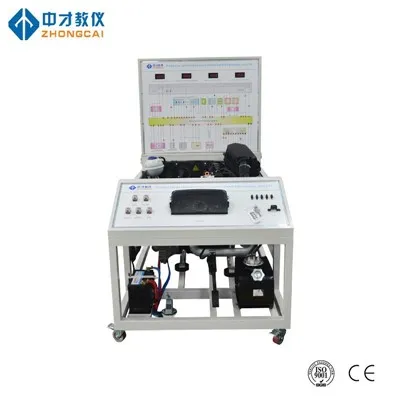
Send Inquiry